Skip to content

Boards and cases

Every Open Lounge Phone is the same small open circuit board inside whatever body suits the room. The board, its firmware and every case are code in the repository, so you can build one, change one or design your own.

  • An ESP32-S3 with Wi-Fi
  • 12 swappable mechanical keys and a hook switch, and a small e-paper status display
  • a 3.5 mm jack for an off-the-shelf classic G-style handset
  • a piezo ringer, one status light, and USB-C for power and updates (no battery)

No microphone on the board. The only microphone is in the handset: unplug the handset and there is no microphone connected at all, and while it is hung up the software keeps it muted. The phone is powered like a landline, from the wall: not a mobile device.
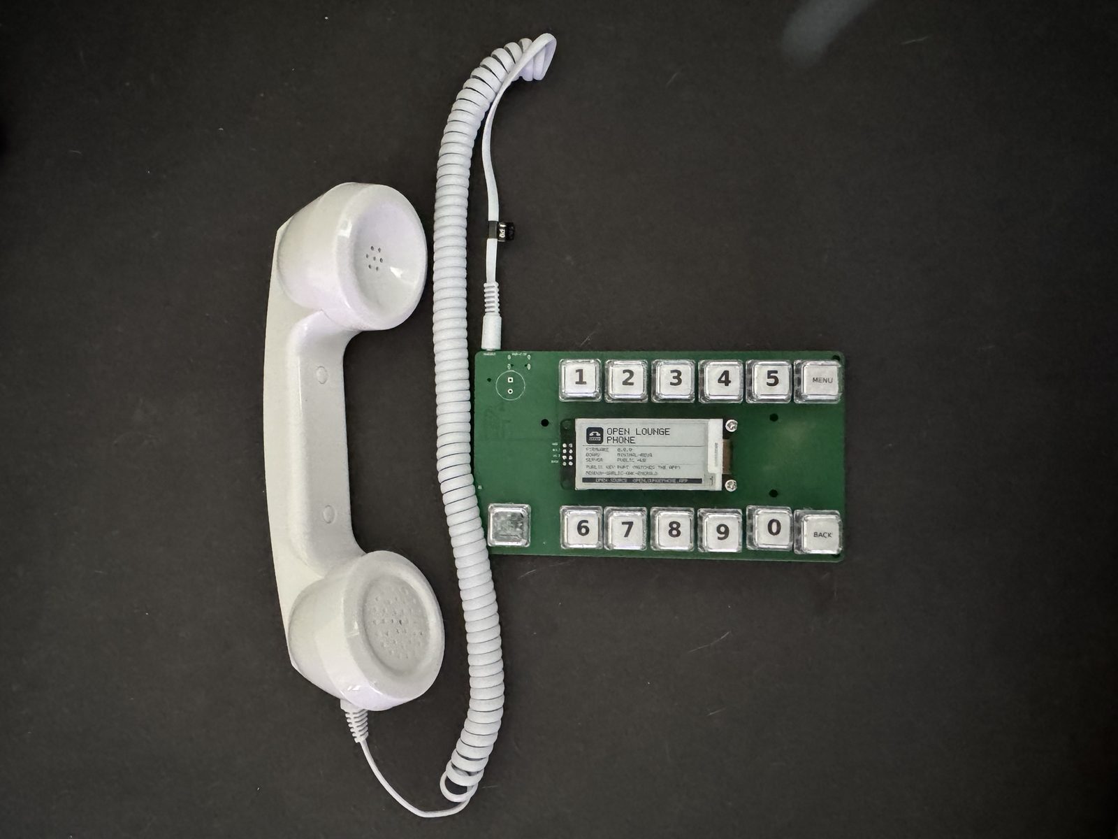
A green v0.1 dev board with twelve clear keycaps in two rows, an e-paper display between them, and a white handset on a coiled cord plugged into its jack
Board v0.1 with a classic handset plugged into its 3.5 mm jack.
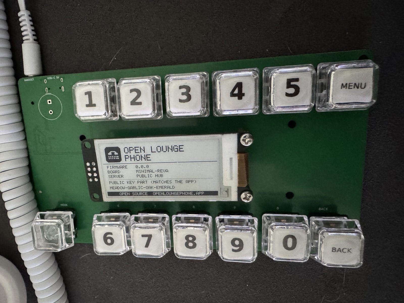
Close-up of the dev board's e-paper display showing Open Lounge Phone, firmware 0.0.0, board minimal-revA, server public hub, and the four words of its key
Its About screen: firmware, board, server, and the four words that match the app.

The first board, built and working (rev A). The release has the exact Gerbers, parts lists, schematic and a build guide.
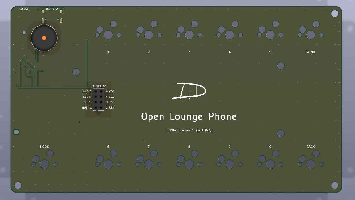
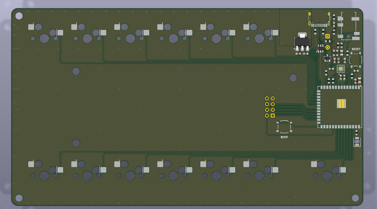
Top of the board: twelve key positions in two rows, a hook switch, the 2x4 display socket, the handset and USB-C edge, and the Open Lounge Phone signature
Top: 12 hot-swap MX keys, a hook switch, the socket for the e-paper module and the piezo ringer.
Bottom of the board with the ESP32-S3 module, audio codec, voltage regulator and USB-C port
Bottom: the ESP32-S3 module, the ES8311 audio codec, the regulator and USB-C. JLCPCB assembles all of it.

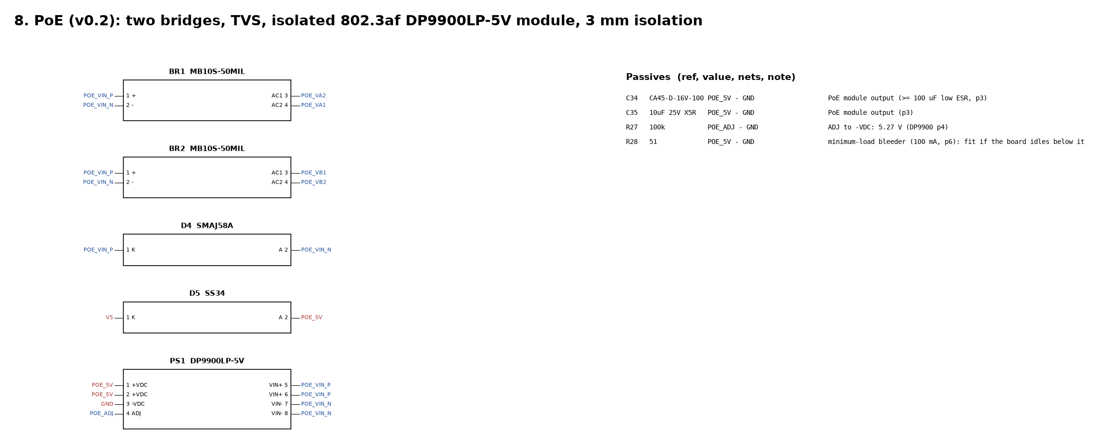
The next revision adds an RJ45 jack, so the phone can run on a network cable instead of Wi-Fi, and PoE: one cable for network and power, like an office desk phone. USB-C still works, and either one powers the phone. It adds a WIZnet W5500 Ethernet chip, a jack with built-in magnetics, and an isolated 802.3af PoE module. It’s still one board with no I/O expander: the Ethernet chip shares the display’s wires.

It’s designed and checked (schematic checks, power budget, full layout with zero design-rule errors, case fit), but not built or tested yet. The phone firmware already drives the Ethernet chip: with a cable it uses the cable and turns Wi-Fi off, without one it uses Wi-Fi (tested in the simulator so far). Parts come to about $18 a board.

Power: one Ethernet cable from a PoE switch port or a PoE injector (IEEE 802.3af or 802.3at) runs the whole phone, up to 100 m. Or use a USB-C charger. A computer’s USB port is for flashing and the console only, with the PoE cable plugged in too. “Passive” 24 V PoE injectors won’t power it.
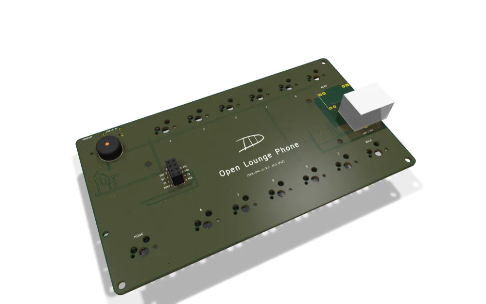
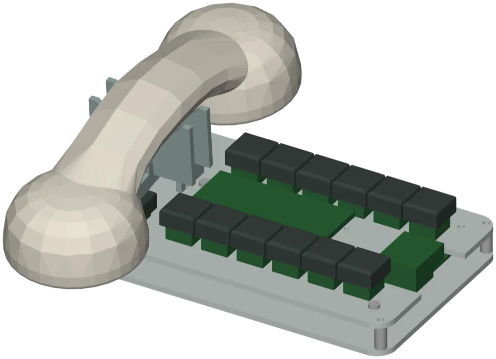
Board v0.2 from above at an angle: the twelve key positions, the hook key, the display socket, the piezo ringer and the RJ45 jack at the right edge
Board v0.2: the RJ45 jack with its PoE module at the right edge (CAD render).
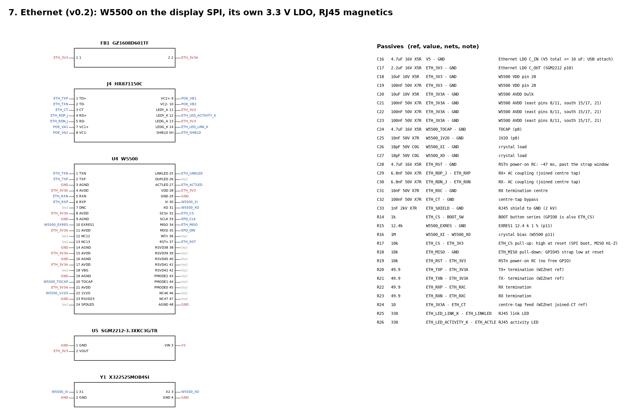
Schematic page: the W5500 Ethernet chip with its pins and nets, the HR871150C RJ45 jack with PoE taps and LEDs, the 3.3 V regulator, the 25 MHz crystal and the list of resistors and capacitors
Ethernet: the W5500 on the display’s SPI wires, its own 3.3 V regulator, and the RJ45 jack.
Schematic page: two bridge rectifiers from the RJ45's PoE pairs, a 58 V TVS diode, the DP9900LP-5V isolated PoE module and the Schottky diode into the 5 V rail
PoE: both cable pair options through bridges and a surge diode into the isolated 5 V module.

The full review is one PDF with a page for every block.
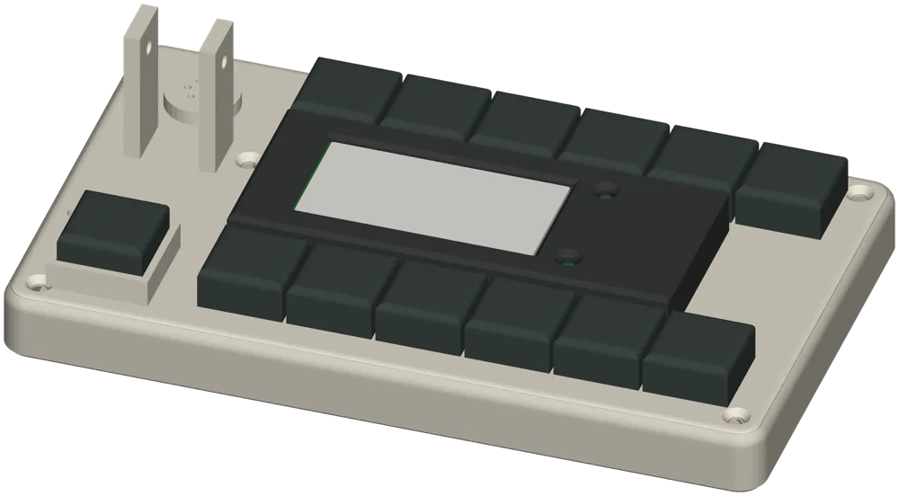
The printed prototype box with twelve keycaps, the hook key at the left and the e-paper display between the rows
Desk box · 3D printed · the handset rests on a hinged cradle over the hook key
A laser-cut acrylic desk phone: two clear plates with the board between them, twelve keys, and a handset lying in a hinged cradle
Flat-cut desk phone · one sheet of laser-cut acrylic or plywood, screws and standoffs
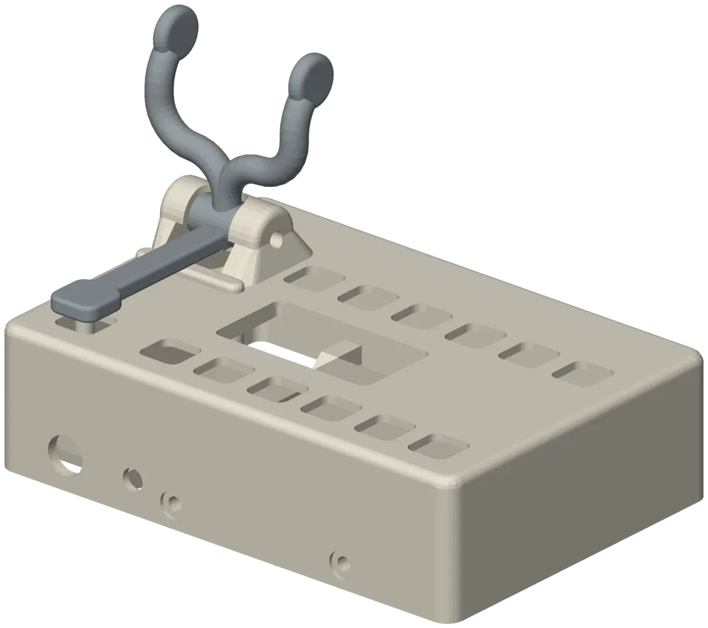
A wall phone faceplate with a forked switchhook on a pivot over the hook key
Wall phone · printed faceplate with a real switchhook, on a wall bracket
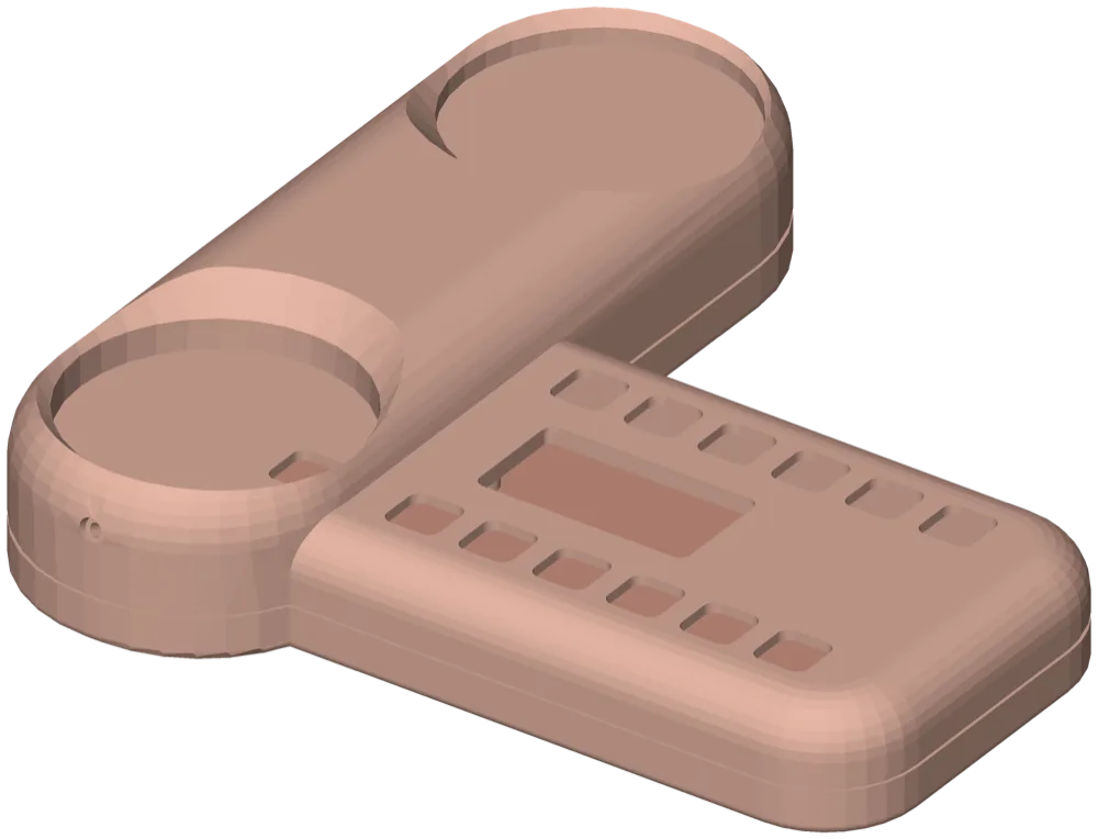
A rounded cushion-like printed case with a cradle for the handset beside the keys
Cushion · a rigid print made to look inflated, with a bed for the handset beside the keys

Pick the colour, keycaps and cord. Every case takes the same board and any CTIA handset.

About $8 in parts per board

The chips, connectors and passives on board v0.1 come to about $8.50 (about $6 in volume). You hand-solder only two parts: the handset jack and the display socket.

About $23 in parts per phone

Board parts plus switches, keycaps, a 2.13” e-paper module and an antenna, with a budget handset (estimates). Board fabrication, assembly and shipping are extra and depend on your order.

Files: hardware v0.1 release (Gerbers, parts list, build guide) · hardware folder (schematic, layout, cases) · Build the hardware.

Proudly supported by unsubscribe.llc · Sponsor the project